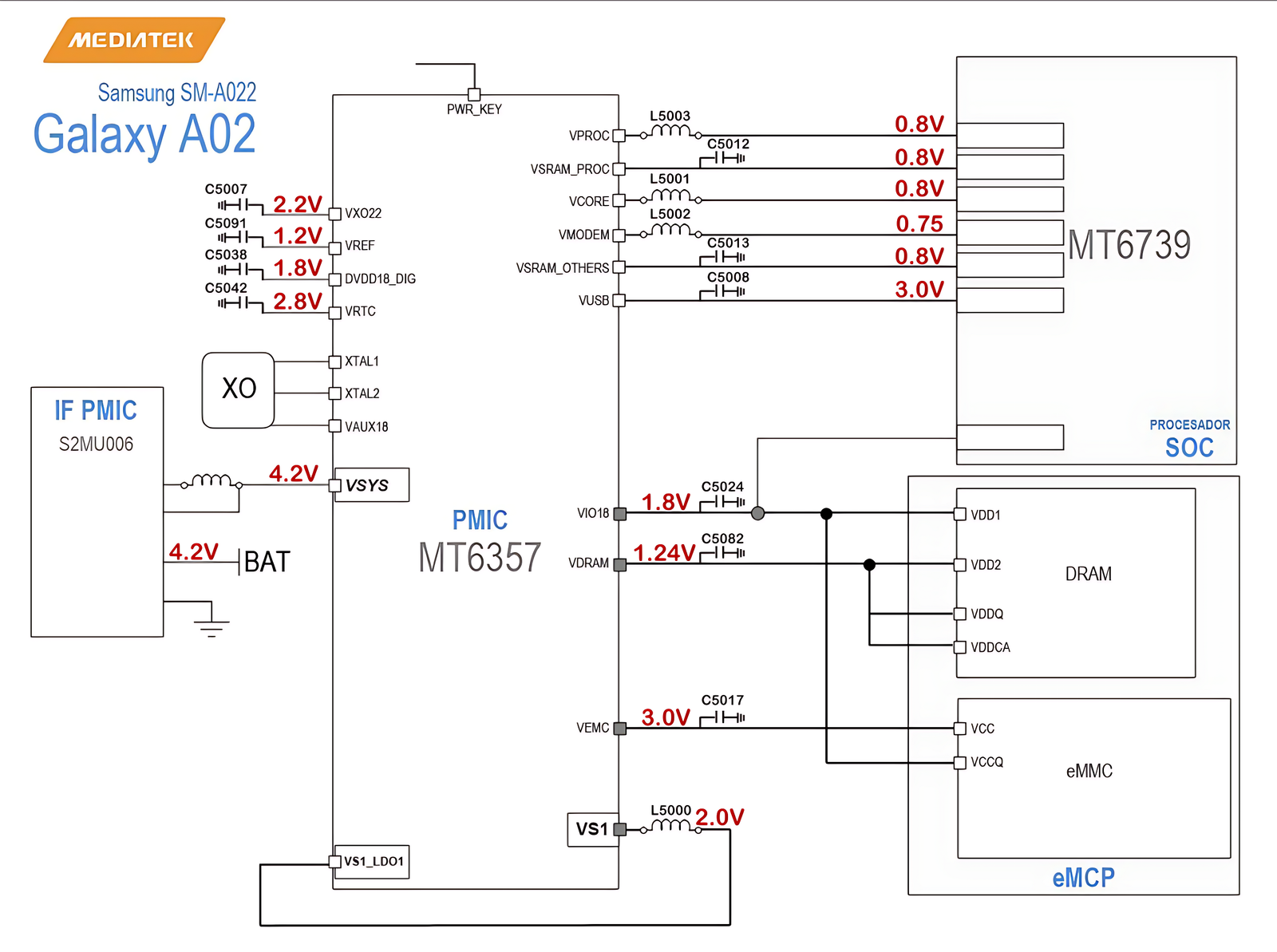
Samsung Galaxy A02 (SM-A022) Power Management: MT6357 & MT6739
Samsung Galaxy A02 (model SM-A022) is powered by the MediaTek MT6739 processor and uses the MT6357 Power Management IC (PMIC) to regulate voltages throughout the device. In this post, we will explain how power is distributed, what each voltage rail does, and why it's important. This guide is based on the power schematic diagram and is ideal for technicians and enthusiasts working on smartphone repair or embedded systems.

🔋 Battery Input and System Voltage
- Battery Voltage (VBAT): 4.2V
- System Voltage (VSYS): 4.2V
The battery supplies 4.2V to the PMIC (MT6357). This voltage is passed to VSYS, which acts as the primary power rail for the entire system. The PMIC uses this voltage to generate different levels required by the SoC, RAM, eMMC, and other subsystems.
⚙️ PMIC: MediaTek MT6357
The MT6357 is a Power Management IC designed to work closely with the MT6739 SoC. It includes multiple LDOs (Low Dropout Regulators) and Buck converters to produce the required voltage levels for various internal and external components. It ensures efficient power distribution and protects against overvoltage, overcurrent, and thermal issues.
🔌 Voltage Rails and Their Roles
1. VX022 – 2.2V
VX022 is a 2.2V line used for analog or RF components, possibly the RF transceiver or other modem-related sections. This voltage rail ensures clean power for noise-sensitive analog circuits.
2. VREF – 1.2V
This is a reference voltage, usually for ADCs (Analog-to-Digital Converters), DACs, or RF circuits. It must be extremely stable, as other systems rely on it for accurate readings.
3. DVDD18_DIG – 1.8V
This supplies digital logic sections inside the SoC or other digital ICs. 1.8V is common for internal core logic or IO buffers.
4. VRTC – 2.8V
This voltage line is used to power the RTC (Real-Time Clock) circuit. It helps maintain timekeeping even when the device is powered off, as long as the battery is connected.
💻 SoC & Processor Power
The MT6739 processor uses several dedicated power rails:
- VPROC – 0.8V: Main CPU core power
- VSRAM_PROC – 0.8V: SRAM (static RAM) inside CPU
- VCORE – 0.8V: Core logic and internal operation
- VMODEM – 0.75V: Modem and baseband processor
- VSRAM_OTHERS – 0.8V: SRAM for other SoC blocks
- VUSB – 3.0V: USB PHY and IO interface
The CPU and internal components require low voltage and high precision for efficient performance and thermal control. These voltages are typically generated by buck converters inside the PMIC.
🧠 DRAM Power Supply
- VIO18 – 1.8V: IO interface for DRAM
- VDRAM – 1.24V: Core voltage for RAM operation
DRAM (main memory) in mobile devices typically operates at lower voltages to reduce power consumption. The interface (I/O) runs at 1.8V while the DRAM core uses 1.24V. The PMIC regulates these voltages to match the memory module's specifications.
💾 eMMC (Storage) Power Supply
- VEMC – 3.0V: Main power for eMMC storage
- VS1 – 2.0V: eMMC IO voltage
The embedded MultiMediaCard (eMMC) is the storage unit of the device. It requires both a core voltage (VEMC) and IO voltage (VS1). These ensure proper read/write operations and data integrity.
📦 Additional Notes
The MT6357 manages power up/down sequences, thermal protection, and dynamic voltage scaling. During boot-up, it powers up components in a specific sequence to avoid system instability. Similarly, it shuts down unused modules to conserve battery.
🔄 Power Sequencing
Here's a simplified boot sequence:
- Battery (4.2V) feeds VSYS
- PMIC powers up VRTC, VREF, and DVDD18_DIG
- Core voltages like VPROC and VCORE are enabled
- DRAM and eMMC rails are powered
- Once stable, the SoC begins execution
🔧 Troubleshooting Tips
- If the device is dead, check VSYS (should be 4.2V)
- Check VPROC and VCORE (should be 0.8V) – if missing, PMIC or SoC may be faulty
- VEMC and VIO18 must be present for storage access
- Use an oscilloscope to confirm stable voltage outputs
📊 Summary Table
| Voltage Rail | Value | Purpose |
|---|---|---|
| VBAT / VSYS | 4.2V | Battery and main system input |
| VX022 | 2.2V | Analog circuits |
| VREF | 1.2V | Reference voltage |
| DVDD18_DIG | 1.8V | Digital logic power |
| VRTC | 2.8V | Real-time clock |
| VPROC / VCORE / VSRAM | 0.8V | CPU and SRAM power |
| VMODEM | 0.75V | Modem power |
| VUSB | 3.0V | USB PHY |
| VIO18 | 1.8V | DRAM IO |
| VDRAM | 1.24V | DRAM Core |
| VEMC | 3.0V | eMMC Core |
| VS1 | 2.0V | eMMC IO |
✅ Conclusion
The Samsung Galaxy A02 uses a well-structured power architecture managed by the MT6357 PMIC. Understanding how each voltage line works helps in diagnosing faults, repairing dead phones, and designing efficient embedded systems. From the battery to the CPU, RAM, and storage, each component has dedicated power rails that must be stable and within tolerance for the device to function properly.
