
Understanding IC 1P 9F A22 - Pinout, Functions
The IC labeled 1P 9F A22 is a power management or battery charging IC. It is used in many mobile phones to handle battery charging, USB power input, and power distribution to the phone’s motherboard. This IC plays a very important role in the working of any mobile phone. If this IC is damaged, your phone might not charge, might not turn on, or might show issues like restarting or overheating.

What is This IC?
This IC is most likely a PMIC (Power Management IC) or a Battery Charger IC. It connects to various parts of the phone: battery, USB input, system output, charging control, temperature sensor, and communication lines. These ICs protect your battery from overcharging, overheating, and overvoltage. They manage how and when the battery gets charged and when power should be supplied to the phone's system.
Pinout and Their Meanings
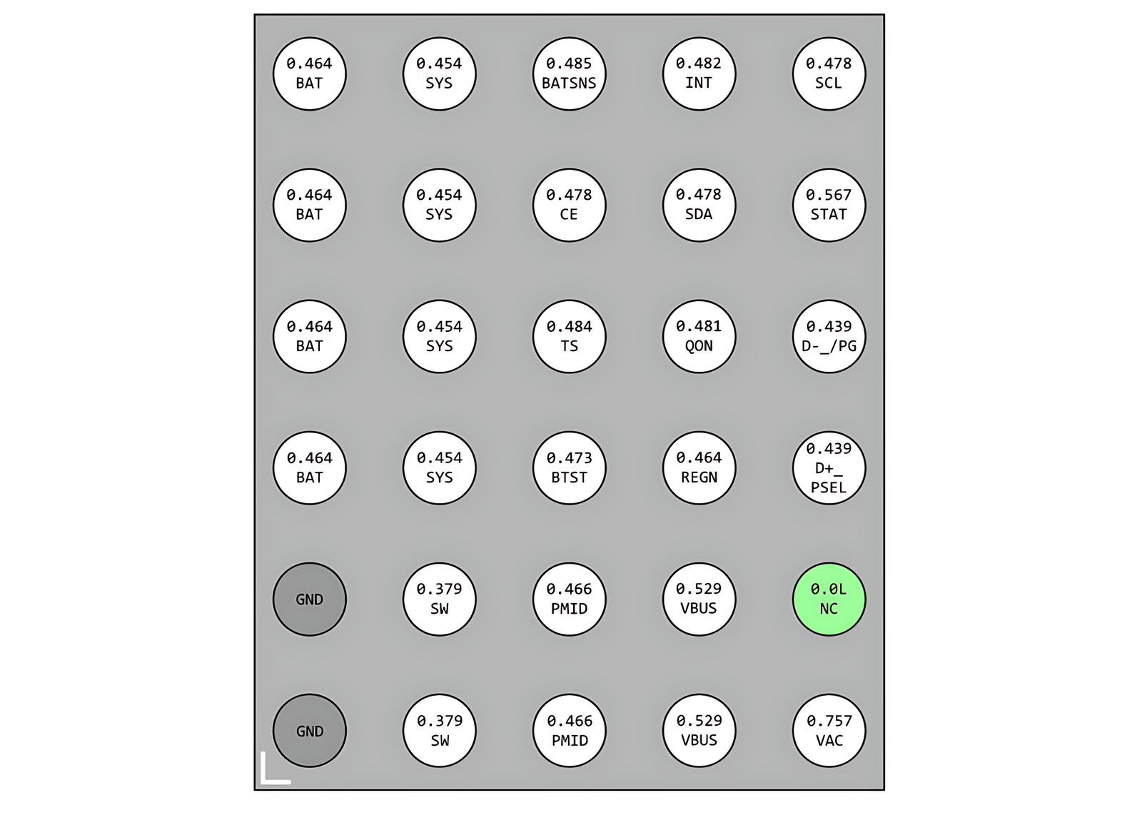
Let’s understand the different pins of this IC and what they do:
- BAT: This is the Battery pin. It connects to the battery’s positive terminal (B+). It is used to charge the battery or provide battery power to the IC.
- SYS: System Output pin. It gives power to the phone’s motherboard (CPU, memory, etc.). If the IC works properly, this pin will have around 3.8V to 4.2V.
- VBUS: USB voltage input. This pin gets 5V from the charger or USB cable. If your charger is working, this pin should show 5V on a multimeter.
- PMID: This is an internal power node. It acts as a bridge between the charger and system/battery. It may show voltage if the IC is switching correctly.
- SW: Switch node. Used for switching power inside the IC. It’s part of the internal buck/boost converter. You may see pulsing signals on an oscilloscope.
- VAC: Adapter input. Optional pin for AC adapters (in some phones). Usually same as VBUS.
- TS: Temperature Sense. It connects to a thermistor on the battery. If the battery gets too hot or too cold, the IC stops charging.
- STAT: Status output. This pin can be used to show charging status with an LED or send a signal to the CPU.
- SDA: Serial Data. This pin is part of I2C communication. The main processor can talk to the IC using this pin.
- SCL: Serial Clock. Works with SDA for I2C communication. It sends the timing signal for data transfer.
- REGN: Regulator output. This provides regulated voltage (often 6V or 3.3V) inside the IC. It powers gate drivers and logic circuits.
- CE: Charge Enable. A control pin to turn ON or OFF the charging process.
- QON: Quick ON. Used to instantly power up the phone or enable fast charging mode.
- INT: Interrupt. Sends a signal to the main processor if a fault or event occurs.
- BTST: Bootstrap pin. Supports internal MOSFET driver for voltage switching.
- D+_PSEL: USB D+ pin or port selection pin. Used to detect charger type (normal, fast charger, etc.)
- D-_PG: USB D- or Power Good pin. Checks if power input is stable and correct.
- NC: Not Connected. This pin has no internal connection. Can be ignored.
- GND: Ground. Common ground reference for the IC and phone circuitry.
Why Is This IC Important?
Without this IC, the phone cannot charge the battery or turn on. It acts like the power controller of the phone. It manages the USB input voltage, charges the battery safely, and gives power to the rest of the phone. If this IC fails, the phone may:
- Stop charging completely
- Show charging symbol but not actually charge
- Overheat while charging
- Keep restarting or boot looping
- Turn off suddenly even if battery is charged
How to Use This IC for Mobile Repair
If a phone is not charging or not turning on, this IC could be the reason. You can follow these steps to troubleshoot:
- Use a multimeter to check the voltage at VBUS. It should be 5V when a USB cable is connected.
- Check BAT pin. It should show the battery’s actual voltage (e.g., 3.7V).
- Check SYS pin. If the IC is working, it will output system voltage (~3.8V to 4.2V).
- If any pin shows 0V or is shorted, the IC may be faulty.
- Use a hot air rework station to remove the IC carefully.
- Replace it with the same IC (BGA type IC needs reballing).
- Clean the board, apply flux, and solder the new IC properly.
- Test again to see if the phone now charges or turns on.
Voltages Expected on Pins
| Pin | Voltage (approx.) |
|---|---|
| VBUS | 5V (from USB charger) |
| BAT | 3.7V to 4.2V |
| SYS | 3.8V to 4.2V |
| REGN | ~6V or 3.3V |
| TS | ~1V (based on thermistor) |
| STAT | 0V or 3.3V (status logic) |
Precautions
- Always check for short circuits before replacing the IC.
- Do not supply voltage if the IC is shorted—it can damage other parts.
- Use ESD protection (ground strap) when handling the IC.
- Use proper tools like a hot air station and microscope for BGA soldering.
Conclusion
The IC labeled “1P 9F A22” is likely a battery charging or power management IC used in many smartphones. It is responsible for safely charging the battery, managing USB power input, and supplying system power to the motherboard. If your phone is not charging or not turning on, this IC could be the cause. By understanding its pinout and function, you can diagnose and repair phones more effectively. Always check voltages on important pins like VBUS, BAT, SYS, and REGN. If faulty, this IC can be replaced carefully with the right equipment and skills.
© 2025 Mobile Repair Guide | All Rights Reserved