Understanding the BQ24192 Battery Charger IC
The BQ24192 is a highly-integrated switch-mode battery charge management and system power path management device by Texas Instruments. It is specifically designed for single-cell Li-Ion and Li-Polymer batteries and is widely used in portable electronics like smartphones, tablets, handheld devices, and IoT gadgets.
🔌 What is BQ24192?
The BQ24192 is a highly efficient, I²C-controlled, 4.5A single-cell charger that supports USB On-The-Go (OTG) functionality and intelligent system power path management. It’s capable of automatically detecting input sources and adjusting charging parameters accordingly. It’s also known for high-speed charging and protection features such as overvoltage, overcurrent, thermal shutdown, and battery temperature monitoring.
📦 Key Features
- Input voltage range: 3.9V to 17V
- Supports USB 2.0, USB 3.0, and adapter input
- Max charging current: 4.5A
- Battery regulation voltage: 4.2V
- I²C Interface for configuration and monitoring
- Thermal regulation and protection
- USB OTG boost operation
📍 Pinout Diagram
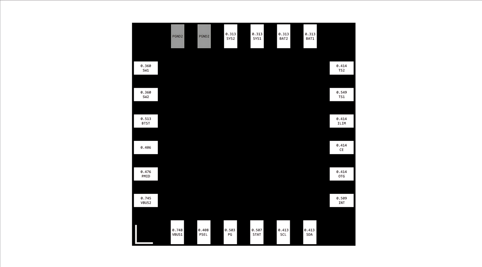
Below is the pinout diagram of the BQ24192 IC:

📌 Pin Descriptions
Here are the meanings of the pins as labeled in the image you uploaded:
- VBUS1 / VBUS2: USB input power (5V typically). Dual pins for improved current handling.
- PGND2: Power ground (return path for high-current switch node).
- SYS1 / SYS2: System output – powers the system when battery or adapter is present.
- BAT1 / BAT2: Battery connection. Connects directly to the battery pack.
- SW1 / SW2: Switch node of the buck converter – connected to internal MOSFETs.
- BTST: Bootstrap capacitor connection for high-side driver.
- PMID: Power output from the input – used internally or for OTG.
- TS1 / TS2: Battery temperature monitoring (NTC thermistor inputs).
- ILIM: Input current limit setting.
- CE: Charge Enable – logic low enables charging.
- OTG: Enables USB OTG boost mode.
- INT: Interrupt output – used to notify the host of faults or charging events.
- PSEL: Power source selection input.
- PG: Power Good indication output.
- STAT: Status indication – shows charging state.
- SCL: I²C Clock line.
- SDA: I²C Data line.
⚙️ Applications of BQ24192
This IC is ideal for many types of battery-powered devices. Common applications include:
- Smartphones and tablets
- Wearable devices
- Power banks
- Medical and industrial handheld tools
- IoT devices with USB charging
- Single-cell Li-Ion/Li-Polymer battery systems
🔧 How It Works
The BQ24192 manages power between three sources:
- Battery
- USB input (VBUS)
- System load
It includes a buck converter that steps down the USB input to charge the battery efficiently. During USB OTG mode, it can also boost the battery voltage to provide 5V output on VBUS, enabling the device to act as a power source (for example, charging another device).
🧠 I²C Control
Through the I²C interface (SCL and SDA pins), the host processor can:
- Enable/disable charging
- Monitor charging status and faults
- Adjust input current limit, charging current, voltage, etc.
🛡️ Safety Features
The BQ24192 includes multiple safety mechanisms to protect both the device and the battery:
- Over-voltage and under-voltage protection
- Thermal regulation and shutdown
- Battery temperature monitoring using NTC thermistors
- Input current limiting
- Watchdog timer
🧾 Conclusion
The BQ24192 IC is a powerful and compact solution for managing battery charging in modern portable electronics. With its intelligent power path management, USB OTG support, and I²C programmability, it offers both flexibility and safety in battery-powered designs.
If you're designing a product that needs efficient and safe single-cell charging, the BQ24192 is a top choice.
